SF Modules – Set 026 – Parking Meter Systems – 01
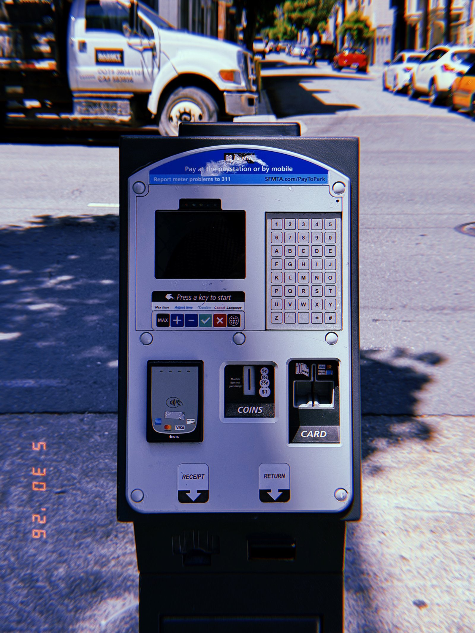
SF Modules — Set 026 “Parking Meter Systems”.
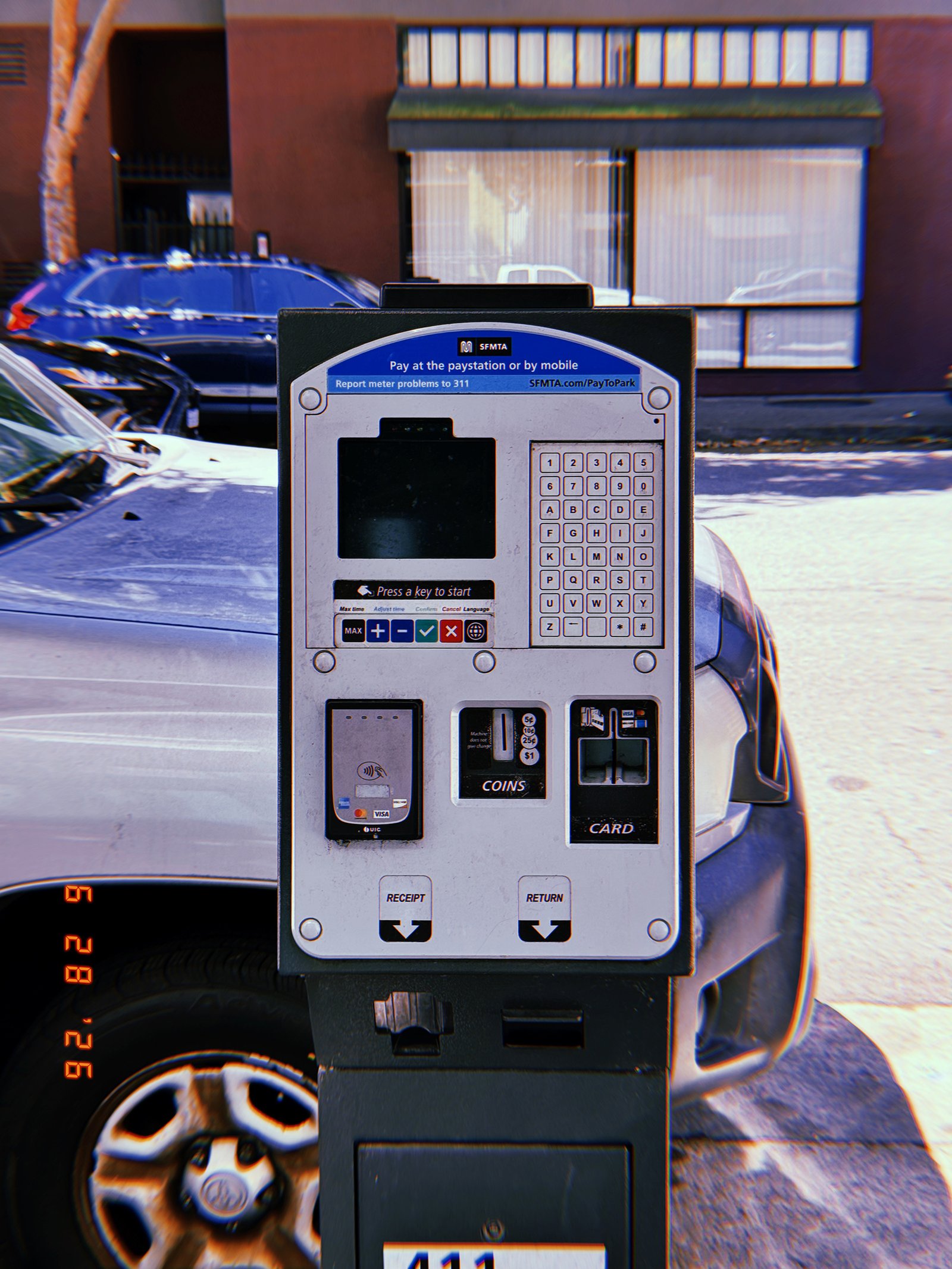
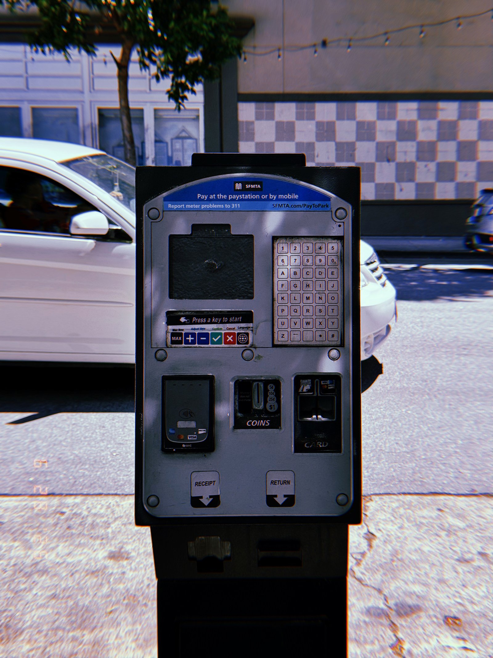
A standardized parking payment kiosk documented from a frontal perspective on a San Francisco street. The interface combines a digital display, alphanumeric keypad, contactless payment reader, coin slot, card terminal, and receipt dispenser into a single public infrastructure device. Repeated throughout the city, these kiosks regulate temporary access to curbside parking through a consistent municipal payment system.
SF Modules – Set 026 – Parking Meter Systems – 02
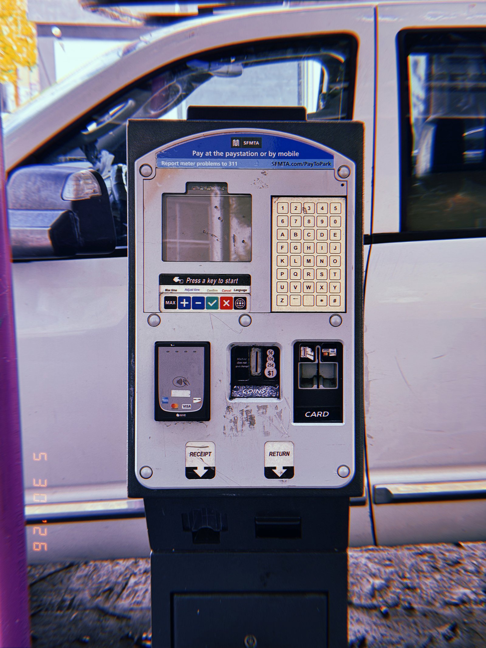
SF Modules — Set 026 “Parking Meter Systems”.
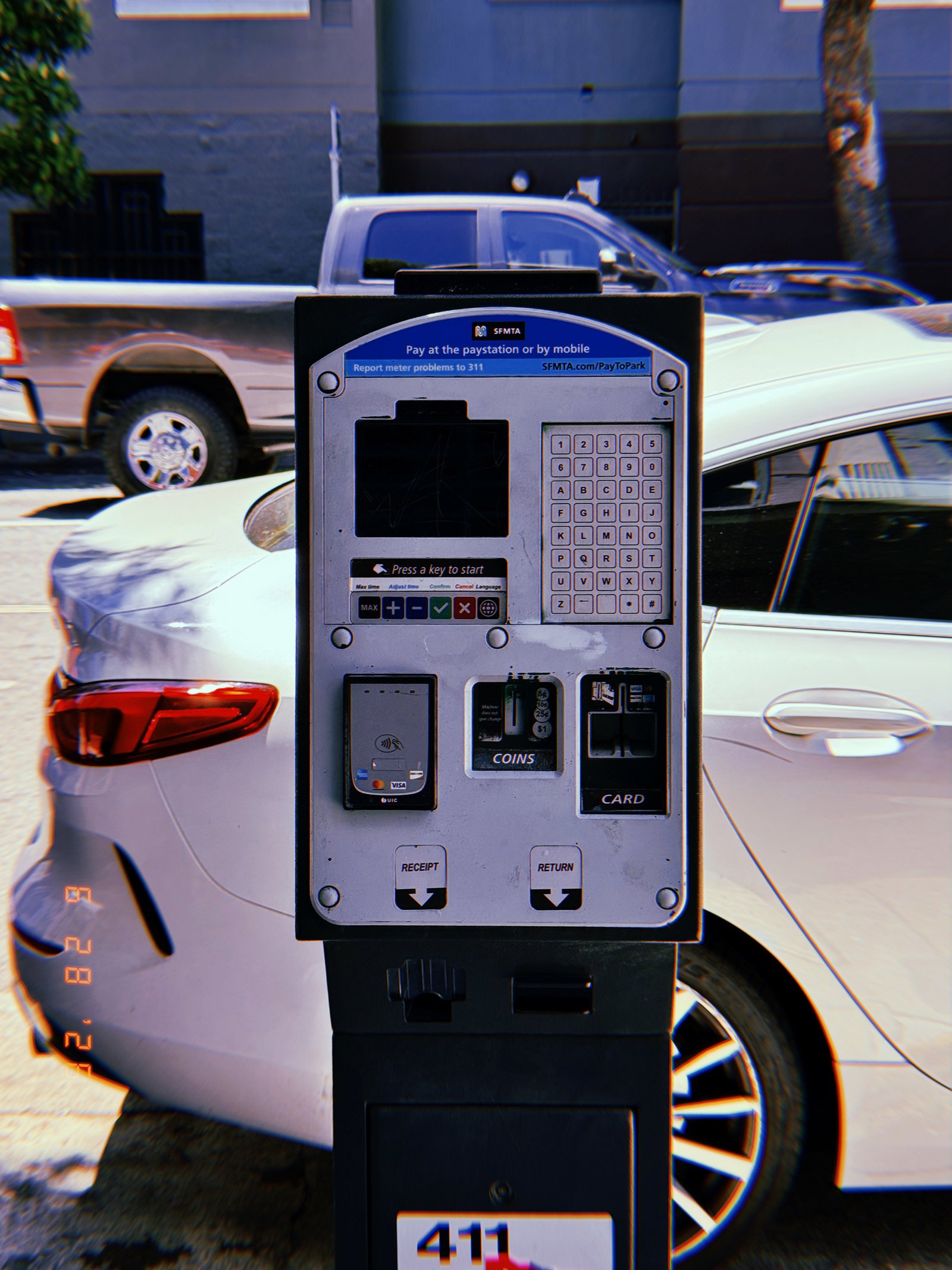
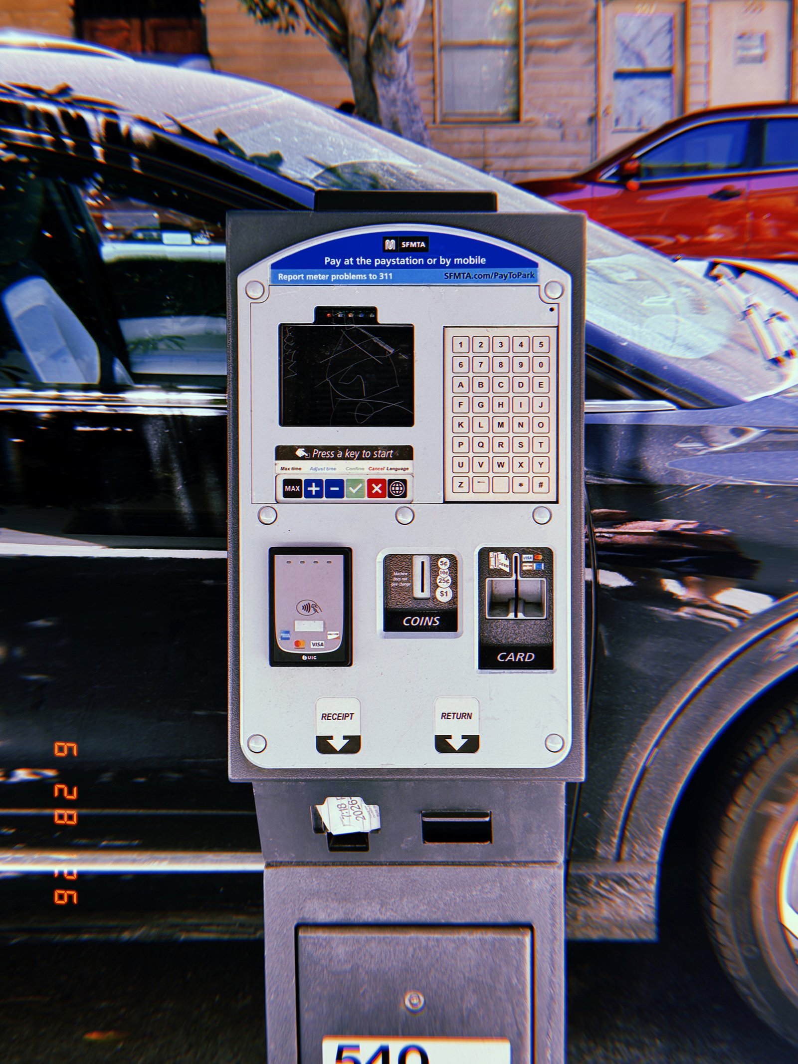
A municipal parking payment kiosk photographed frontally on a San Francisco street. The standardized interface integrates a digital display, keypad, contactless payment reader, coin slot, card terminal, and receipt dispenser into a single public transaction device. Positioned between the sidewalk and parked vehicles, it functions as part of the city’s standardized system for regulating curbside parking.
SF Modules – Set 026 – Parking Meter Systems – 03
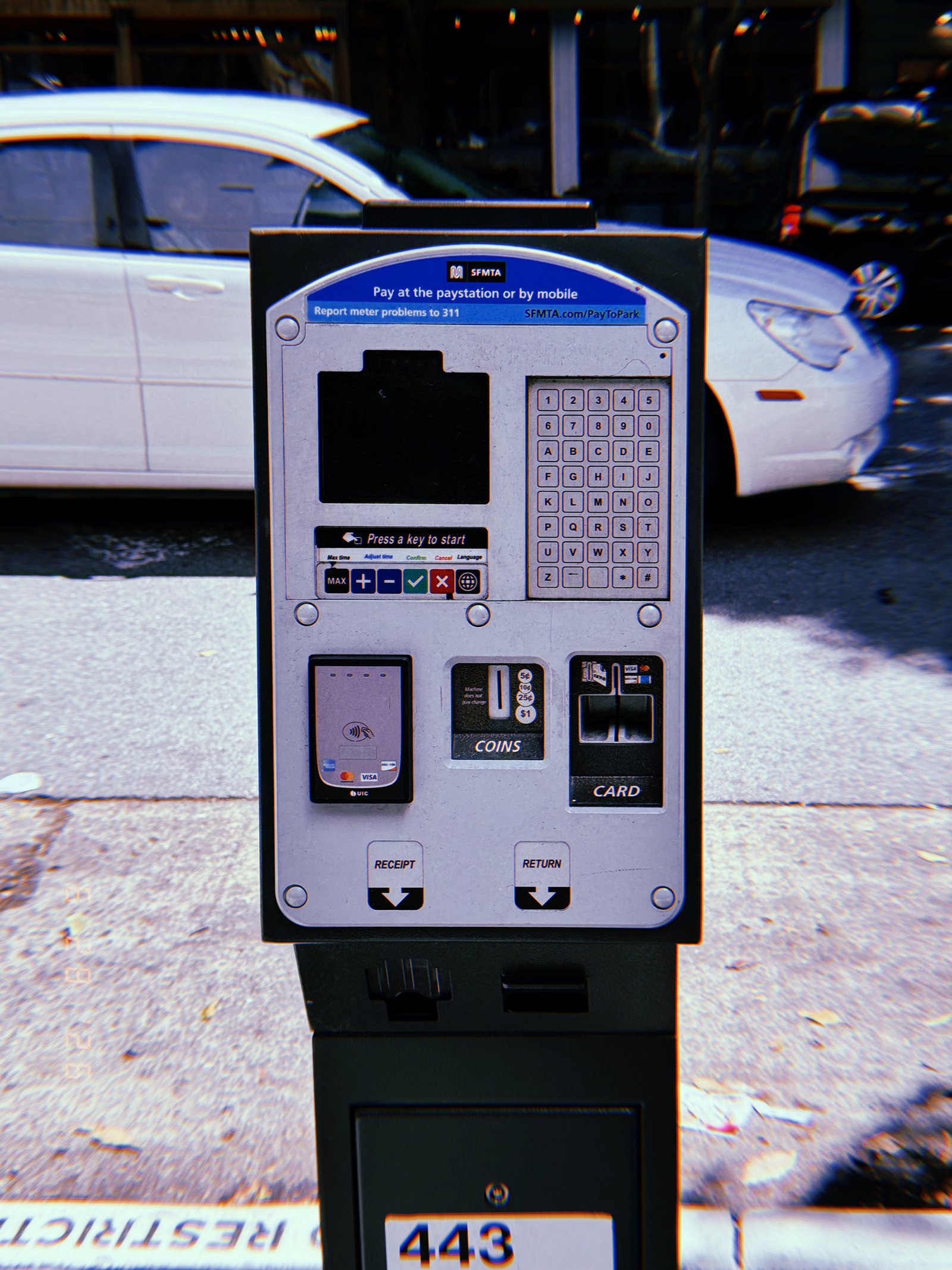
SF Modules — Set 026 “Parking Meter Systems”.
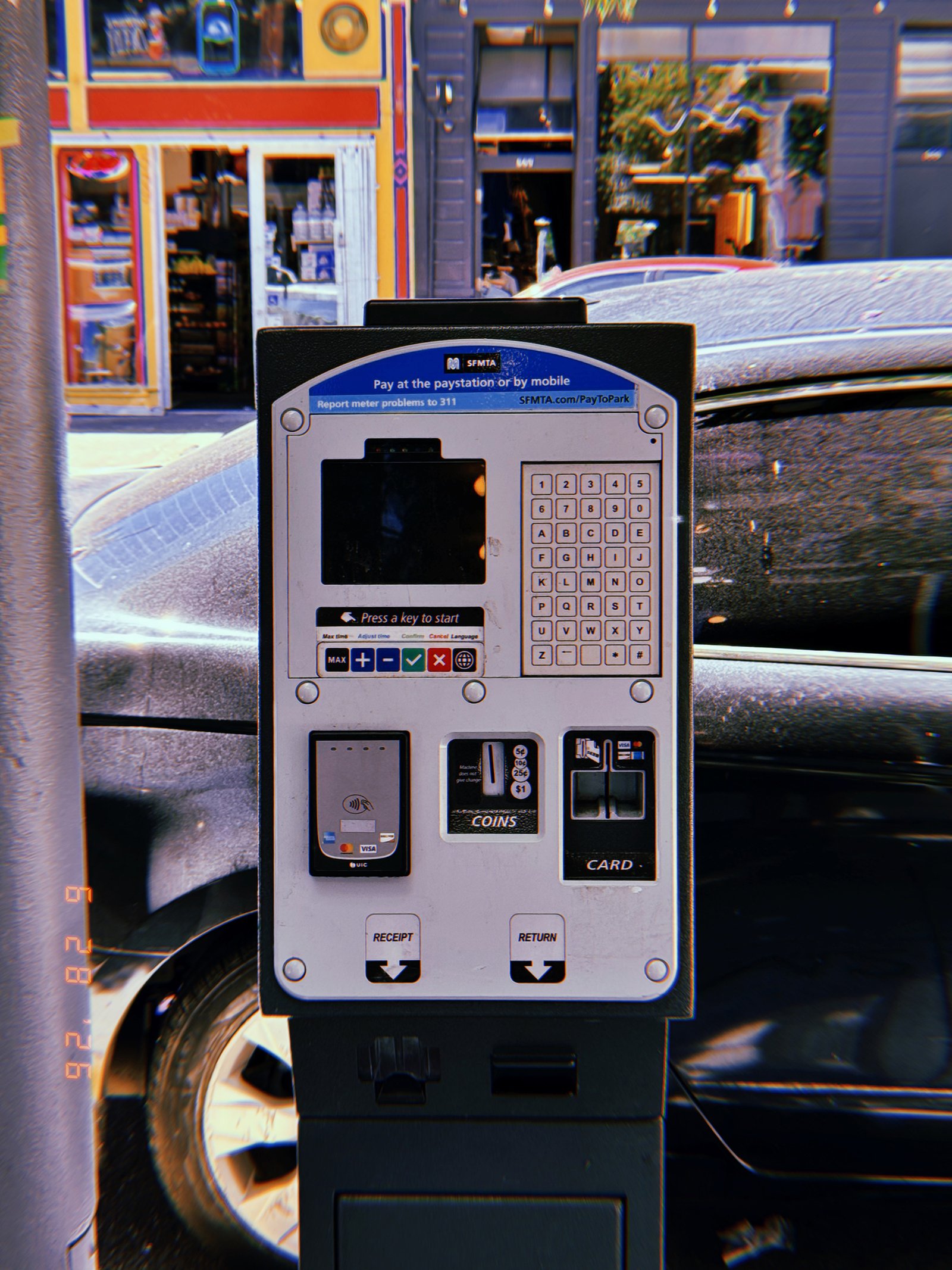
A municipal parking payment kiosk documented frontally along a San Francisco street. The standardized interface combines a digital display, keypad, contactless payment reader, coin slot, card terminal, and receipt dispenser into a single public transaction device. Installed at the edge of the sidewalk, it serves as a fixed transaction point within the city’s curbside parking management system.
SF Modules – Set 026 – Parking Meter Systems – 04
SF Modules — Set 026 “Parking Meter Systems”.
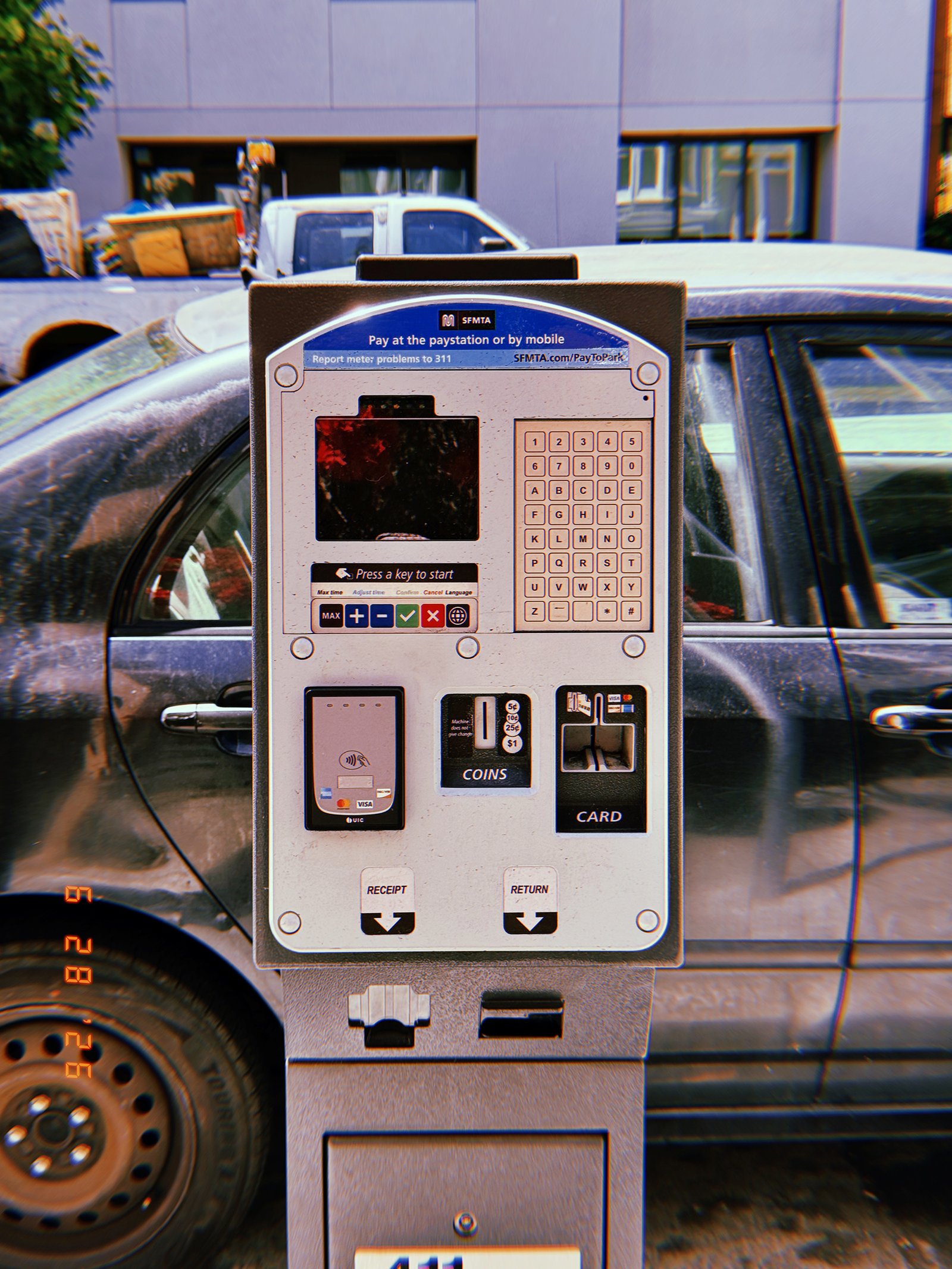
A municipal parking payment kiosk photographed frontally on a San Francisco street. The standardized interface integrates a digital display, keypad, contactless payment reader, coin slot, card terminal, and receipt dispenser into a single public transaction device. Installed directly beside parked vehicles, it functions as a permanent component of the city’s curbside parking infrastructure.
SF Modules – Set 026 – Parking Meter Systems – 05
SF Modules — Set 026 “Parking Meter Systems”.
A municipal parking payment kiosk photographed frontally along a San Francisco street. The standardized unit integrates a digital display, keypad, contactless payment reader, coin slot, card terminal, and receipt dispenser into a single public interface. Installed between parked vehicles and the pedestrian zone, it functions as a permanent transaction point within the city’s curbside parking system.
SF Modules – Set 026 – Parking Meter Systems – 06
SF Modules — Set 026 “Parking Meter Systems”.
A municipal parking payment kiosk photographed frontally within a commercial streetscape in San Francisco. The standardized interface combines a digital display, keypad, contactless payment reader, coin slot, and card terminal into a single public transaction device. Installed between the sidewalk and parked vehicles, it forms part of the city’s system for regulating access to curbside parking.
SF Modules – Set 026 – Parking Meter Systems – 07
SF Modules — Set 026 “Parking Meter Systems”.
A municipal parking payment kiosk documented frontally within the streetscape of San Francisco. The machine combines display, keypad, contactless reader, coin acceptance, and card payment into a standardized interface for regulating curbside parking. Installed directly beside parked vehicles, it functions as a fixed transaction node within the city’s transportation infrastructure.
SF Modules – Set 026 – Parking Meter Systems – 08
SF Modules — Set 026 “Parking Meter Systems”.
A municipal parking payment kiosk photographed frontally on a San Francisco sidewalk. The machine integrates digital display, keypad, contactless payment, coin acceptance, and card processing into a single standardized public interface. Positioned between moving traffic and the pedestrian zone, it operates as a fixed transaction point within the city’s parking infrastructure.
SF Modules – Set 026 – Parking Meter Systems – 09
SF Modules — Set 026 “Parking Meter Systems”.
A digital parking payment kiosk installed along a San Francisco street. The interface combines a display, keypad, payment terminals, and receipt dispenser into a standardized public transaction device. Positioned between parked vehicles, it functions as part of the city’s parking management infrastructure, translating curb space into a regulated and measurable urban resource.
SF Modules – Set 025 – Utility Cabinets – 01
SF Modules — Set 025 “Utility Cabinets”.
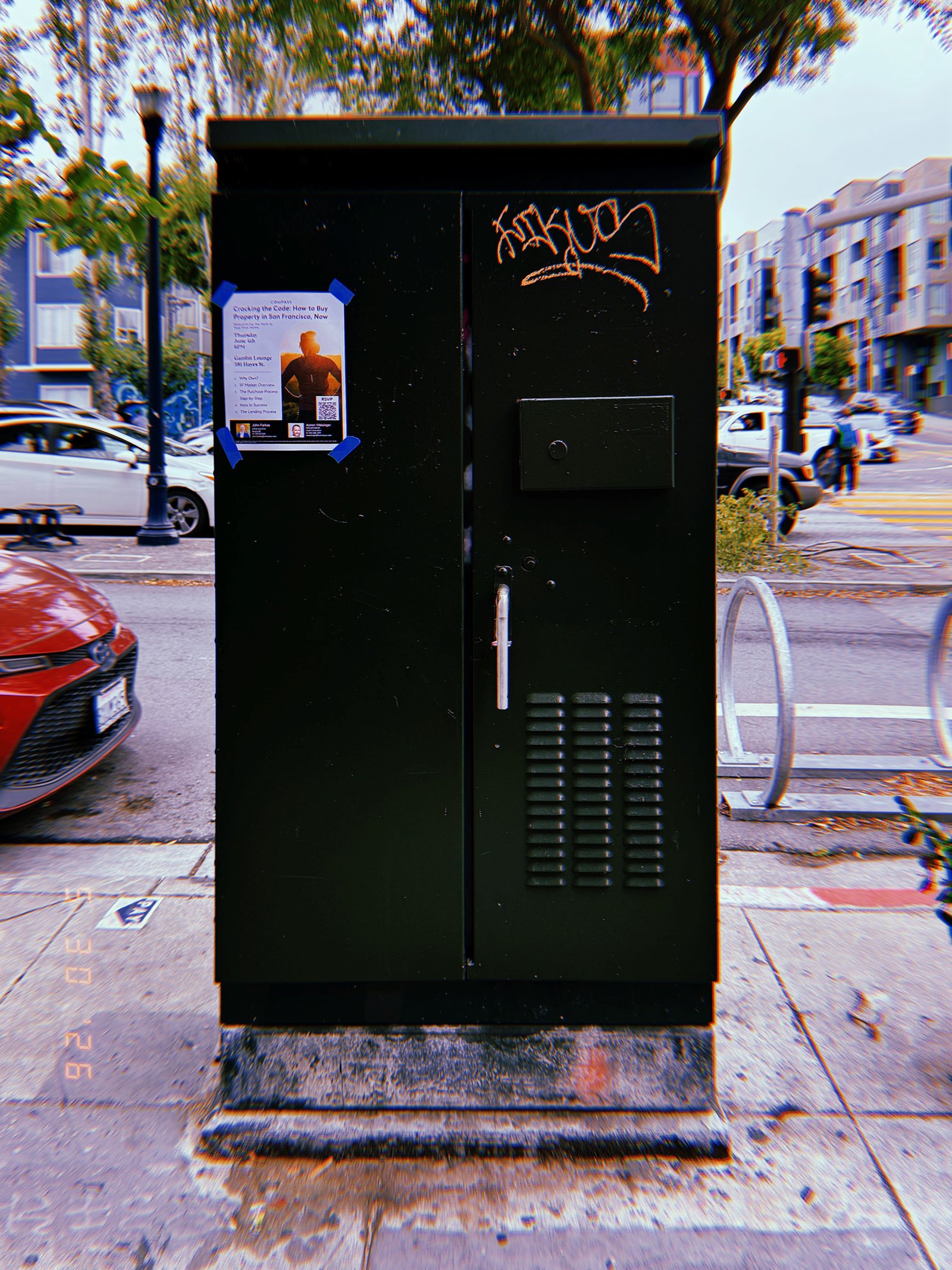
A black utility cabinet stands along a busy San Francisco street, enclosing electrical or communications infrastructure within a standardized metal enclosure. A temporary flyer and graffiti occupy its otherwise functional surface, illustrating how public infrastructure becomes an informal site for notices and intervention. Despite these additions, the cabinet continues to operate as a protected node within the city’s distributed technical network.
SF Modules – Set 025 – Utility Cabinets – 02
SF Modules — Set 025 “Utility Cabinets”.
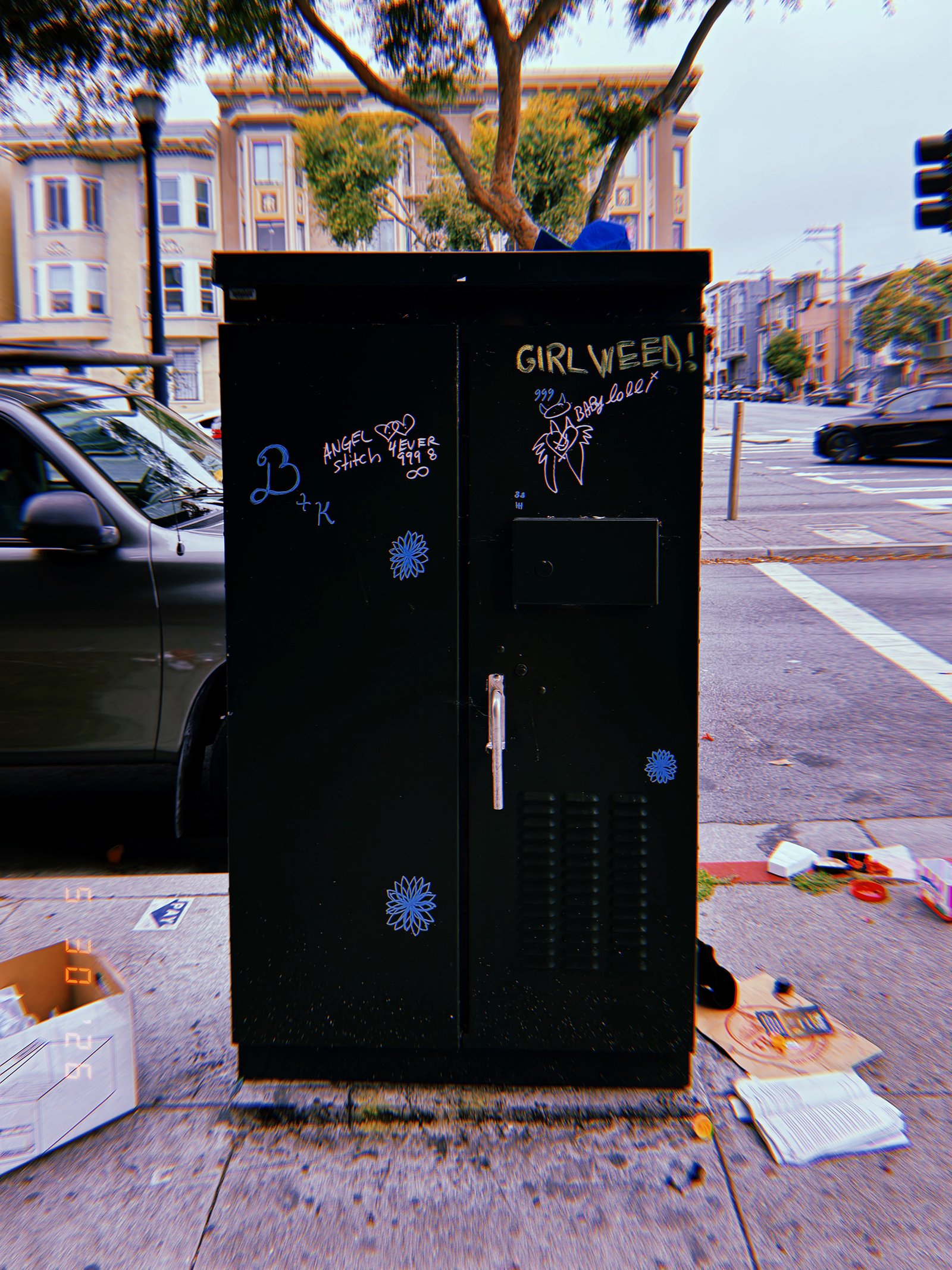
A black utility cabinet stands at a neighborhood intersection, enclosing electrical or communications infrastructure inside a standardized metal enclosure. Graffiti, stickers, handwritten messages, and discarded objects surrounding its base transform the cabinet into a surface of informal public expression while its technical function remains unchanged. The image documents the coexistence of regulated infrastructure and everyday urban intervention.
SF Modules – Set 025 – Utility Cabinets – 03
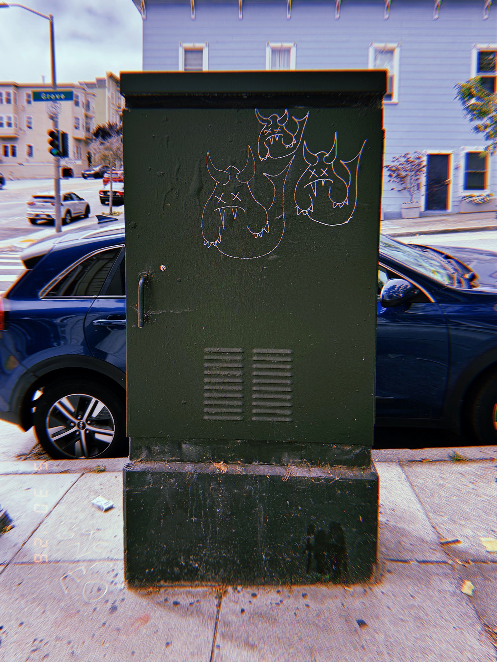
SF Modules — Set 025 “Utility Cabinets”.
A dark green utility cabinet stands on a reinforced concrete base along a neighborhood sidewalk, enclosing electrical or communications infrastructure within a standardized metal enclosure. Small graffiti drawings and weathered paint introduce traces of human activity while leaving the cabinet’s functional role unchanged. The contrast between regulated infrastructure and informal intervention reveals the layered conditions of the urban environment.
SF Modules – Set 025 – Utility Cabinets – 04
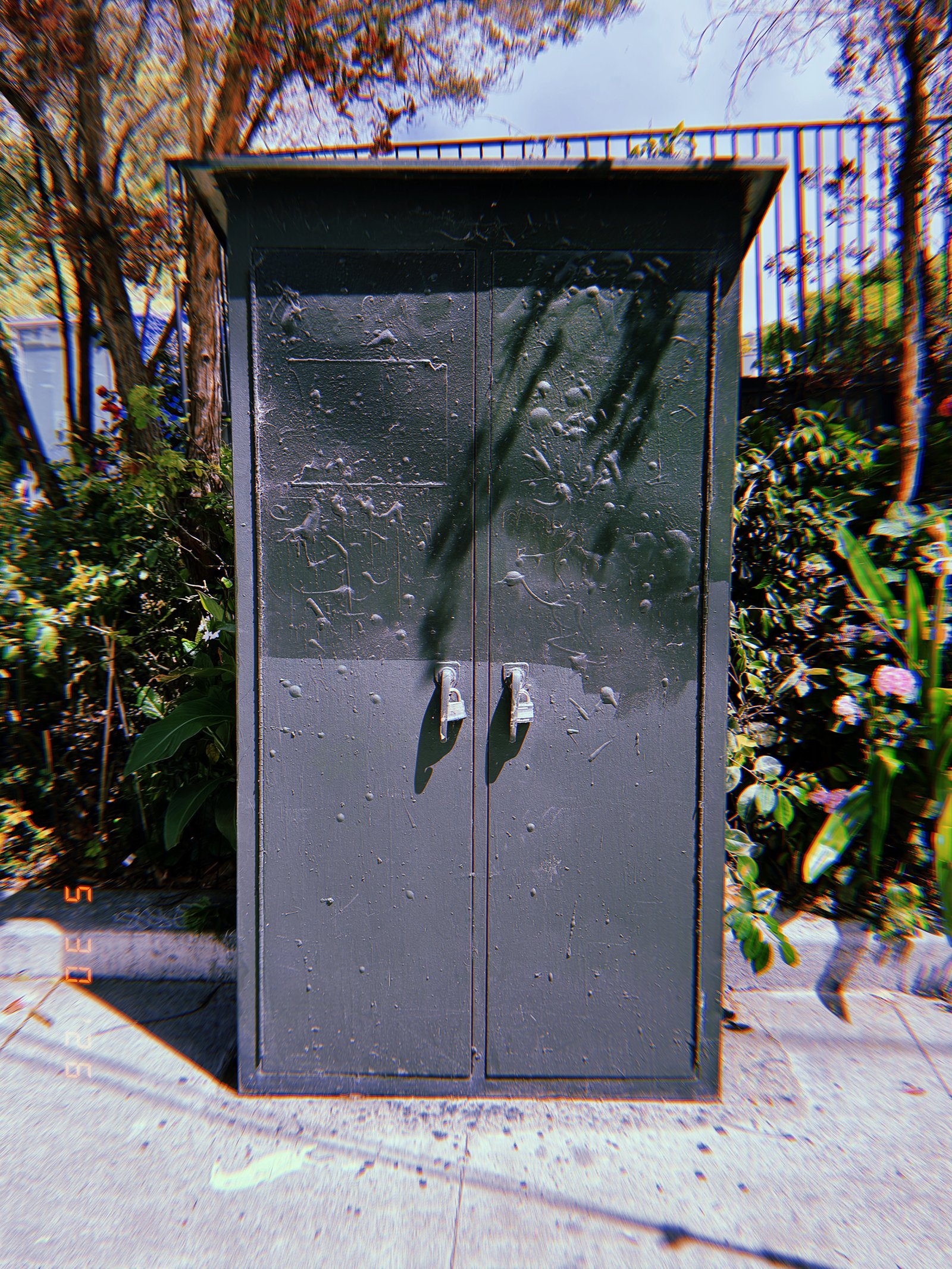
SF Modules — Set 025 “Utility Cabinets”.
A tall gray utility cabinet stands along a residential sidewalk, enclosing electrical or communications infrastructure inside a secure metal housing. Twin access doors, locking handles, and a projecting roof reinforce its function as protected service infrastructure. Weathered surfaces and accumulated traces of use reveal the cabinet as a long-term component of San Francisco’s distributed urban network.
SF Modules – Set 025 – Utility Cabinets – 05
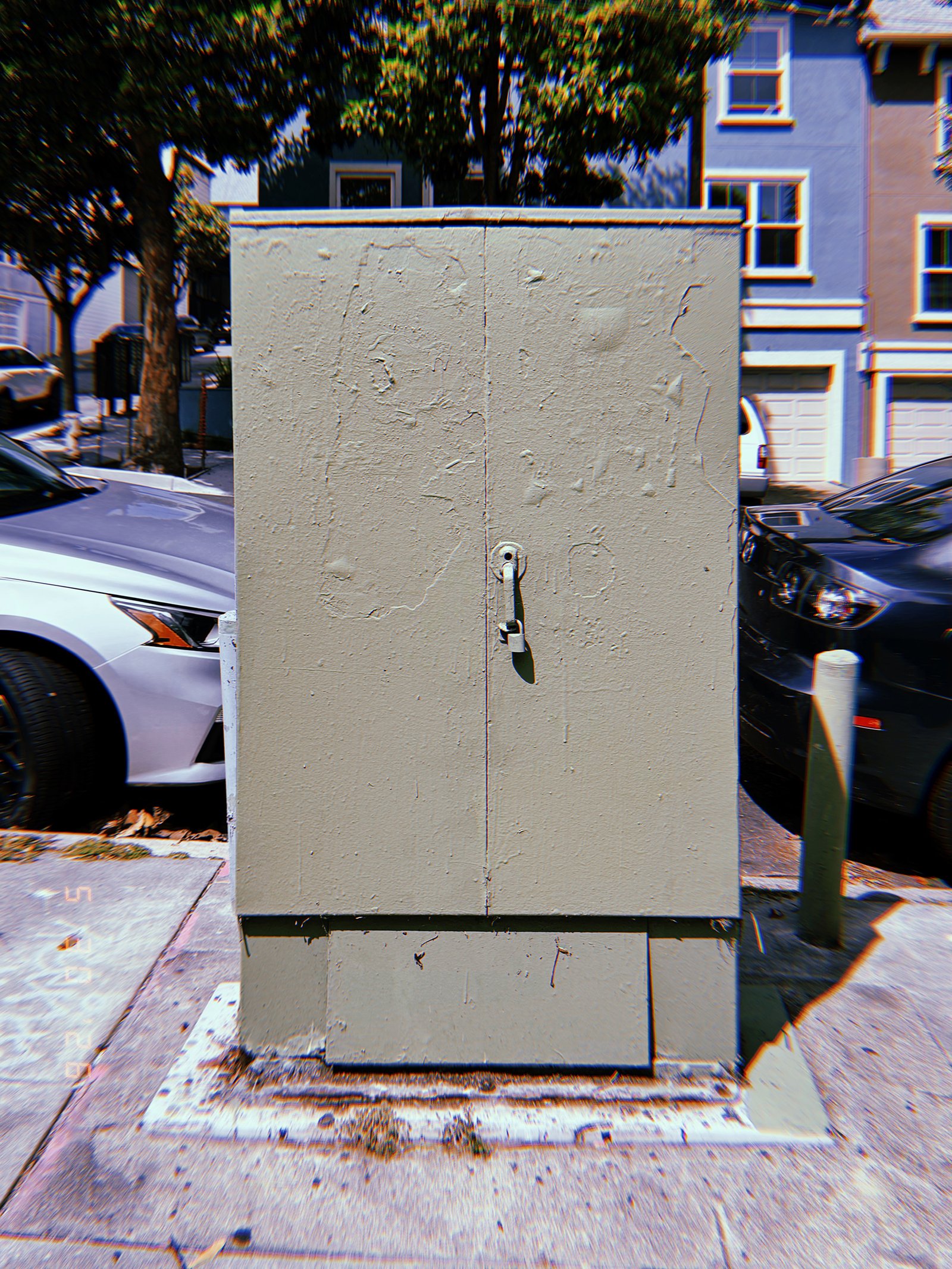
SF Modules — Set 025 “Utility Cabinets”.
A light gray utility cabinet stands on a reinforced concrete base beside a residential street, enclosing electrical or communications infrastructure within a standardized metal enclosure. Its flat doors, central locking mechanism, and minimal form emphasize controlled access and long-term durability. Integrated into the everyday streetscape, the cabinet functions as a discreet node within San Francisco’s distributed infrastructure network.
SF Modules – Set 025 – Utility Cabinets – 06
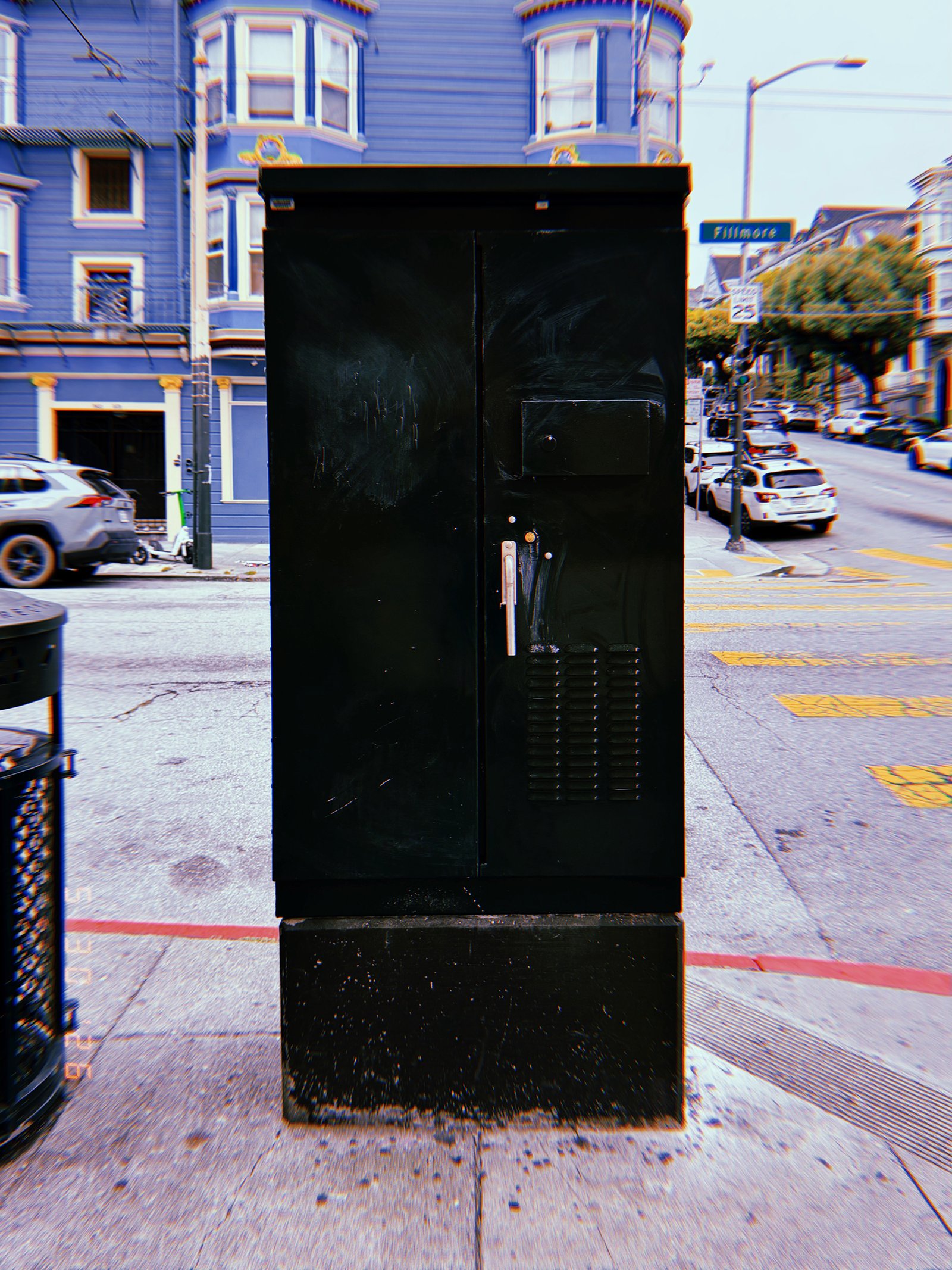
SF Modules — Set 025 “Utility Cabinets”.
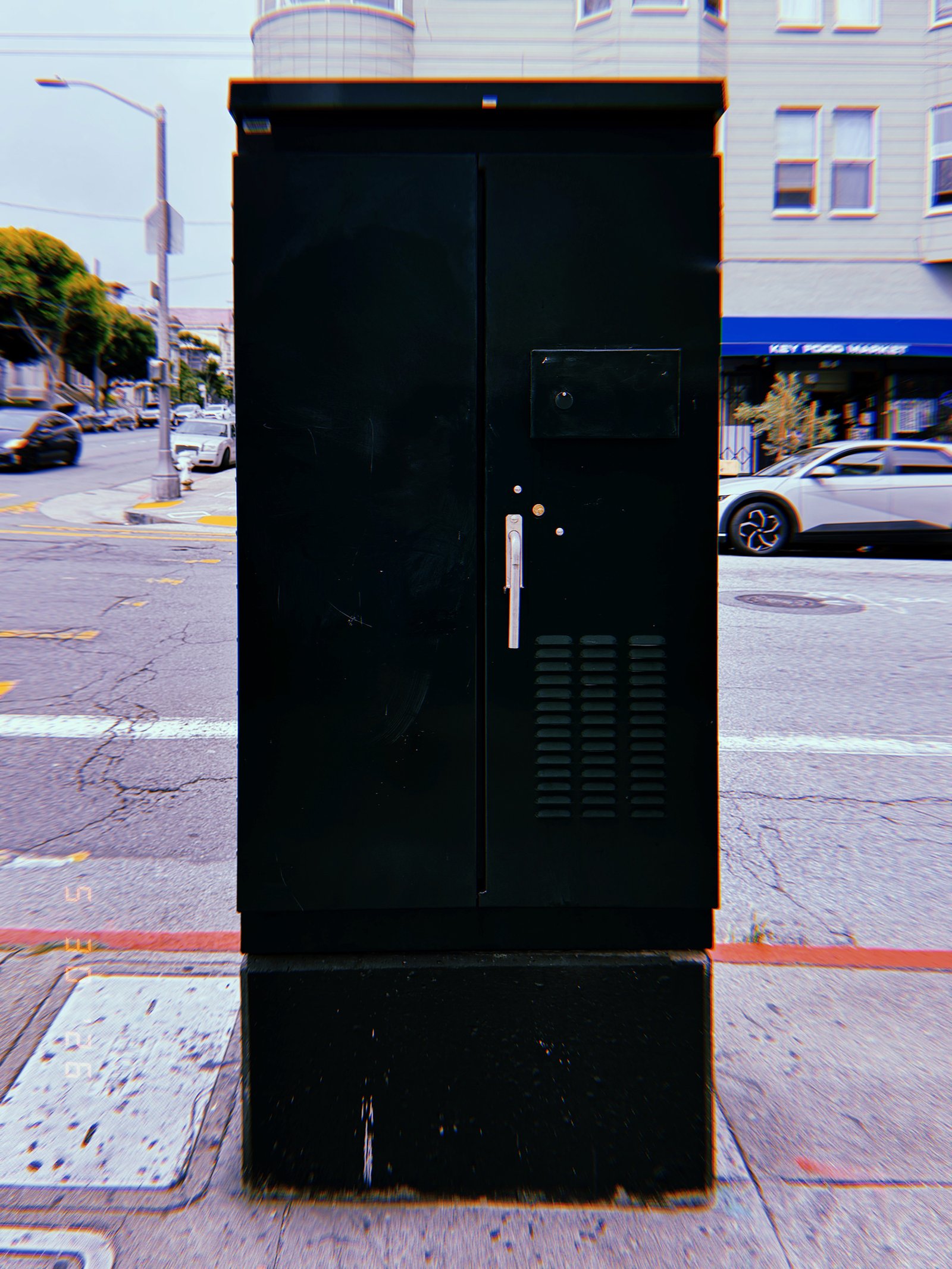
A freestanding black utility cabinet stands at a busy San Francisco intersection, housing electrical or communications infrastructure inside a standardized metal enclosure. Locking hardware, ventilation slots, and reinforced construction define its service function while concealing the systems it protects. Positioned within the flow of traffic and pedestrians, the cabinet operates as a discreet node in the city’s distributed infrastructure network.
SF Modules – Set 025 – Utility Cabinets – 07
SF Modules — Set 025 “Utility Cabinets”.
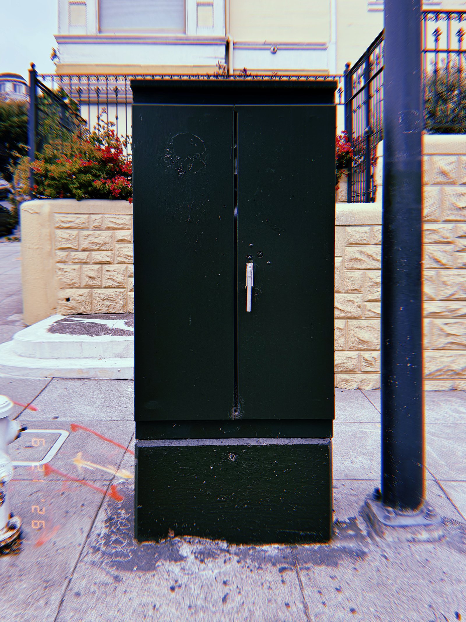
A freestanding black utility cabinet occupies a street corner, enclosing electrical or communications infrastructure within a secure metal housing. Access panels, ventilation slots, and locking hardware reveal its maintenance function while concealing the systems operating inside. Positioned at the intersection of public space and technical infrastructure, it serves as a standardized node within San Francisco’s urban network.
SF Modules – Set 025 – Utility Cabinets – 08
SF Modules — Set 025 “Utility Cabinets”.
A freestanding utility cabinet stands on a reinforced concrete base along a San Francisco sidewalk. Its smooth steel doors, locking hardware, and standardized proportions identify it as a protected enclosure for electrical or communications infrastructure. Positioned within the streetscape, the cabinet functions as a secure maintenance node supporting the city’s distributed technical systems.
SF Modules – Set 025 – Utility Cabinets – 09
SF Modules — Set 025 “Utility Cabinets”.
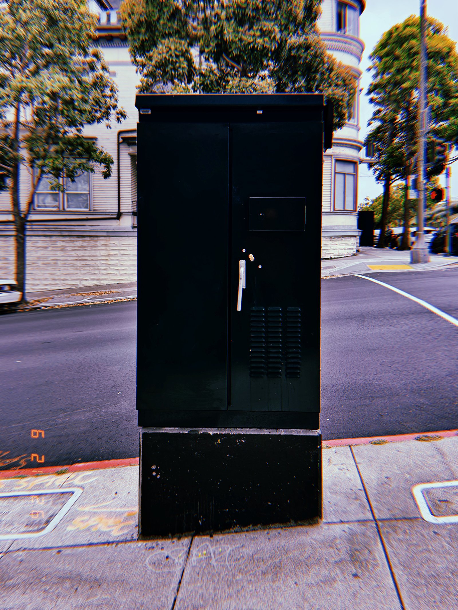
A freestanding utility cabinet is positioned on a concrete base at a street intersection, enclosing electrical or communication infrastructure within a secure metal housing. Access panels, ventilation openings, and locking hardware define its maintenance function while concealing the technical systems inside. Installed along the public right-of-way, the cabinet operates as a standardized node within the city’s distributed infrastructure network.
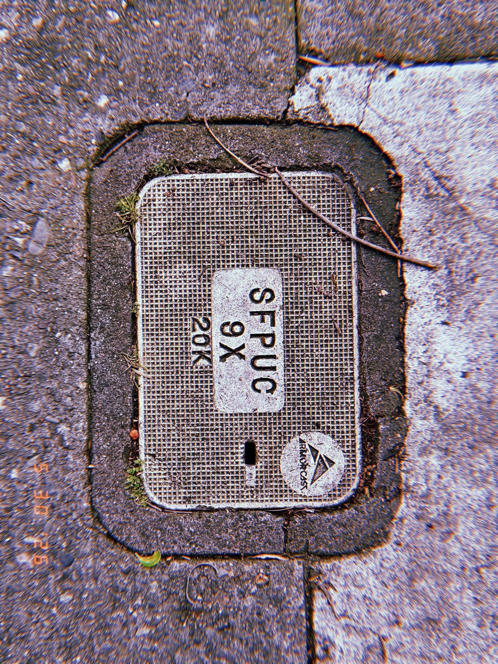
SF Modules – Set 024 – Access Covers – 01
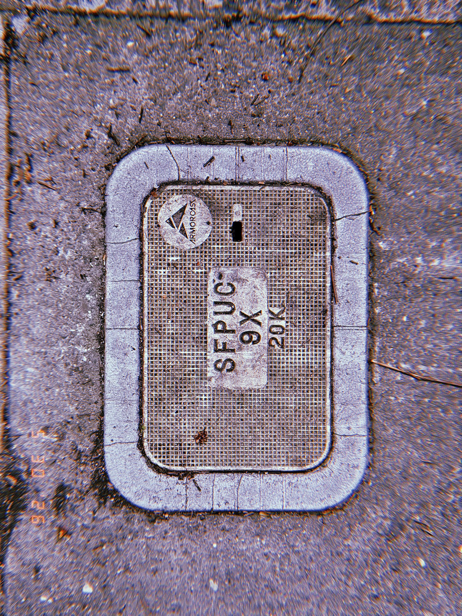
SF Modules — Set 024 “Access Covers”.
A communications access cover is integrated into the sidewalk surface, forming a maintenance interface between public space and underground network infrastructure. The textured panel contains utility identification markings and service access points used for inspection and maintenance operations. Embedded within the pavement grid, the cover functions as a standardized component of the city’s communication systems.
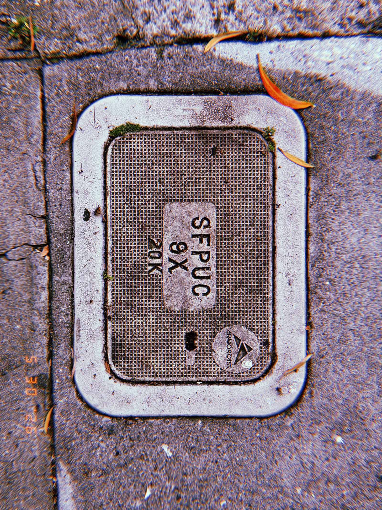
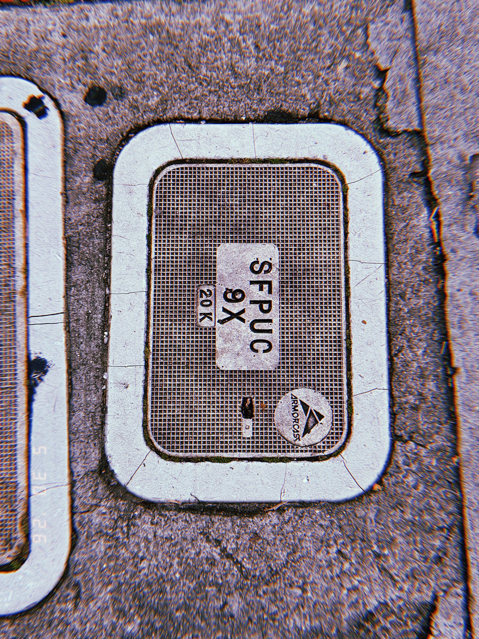
SF Modules – Set 024 – Access Covers – 02
SF Modules — Set 024 “Access Covers”.
A communications access cover is embedded within the sidewalk surface, creating a maintenance interface between public space and underground network infrastructure. The textured panel contains utility identification markings and service access points used for inspection and maintenance operations. Integrated into the pavement grid, the cover functions as a standardized component of the city’s communication systems.
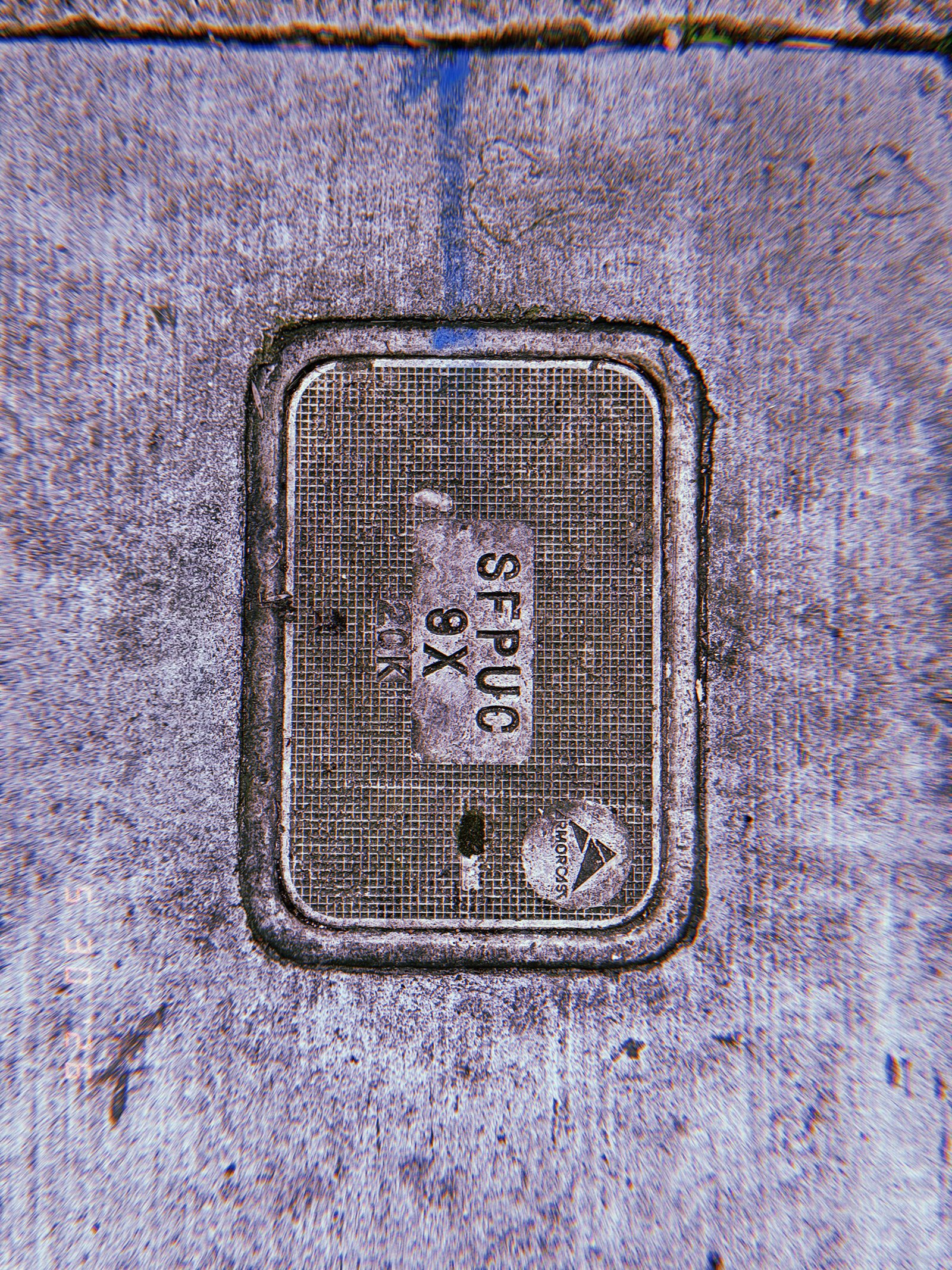
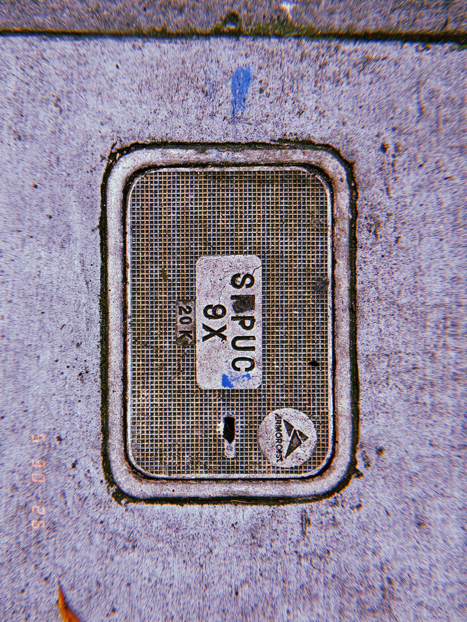
SF Modules – Set 024 – Access Covers – 03
SF Modules — Set 024 “Access Covers”.
A communications access cover is integrated into the sidewalk surface, forming a maintenance interface between public space and underground network infrastructure. The textured panel contains utility identification markings and service access points used for inspection and maintenance operations. Surrounded by paving joints, vegetation, and surface debris, the cover functions as a standardized component within the city’s communication systems.
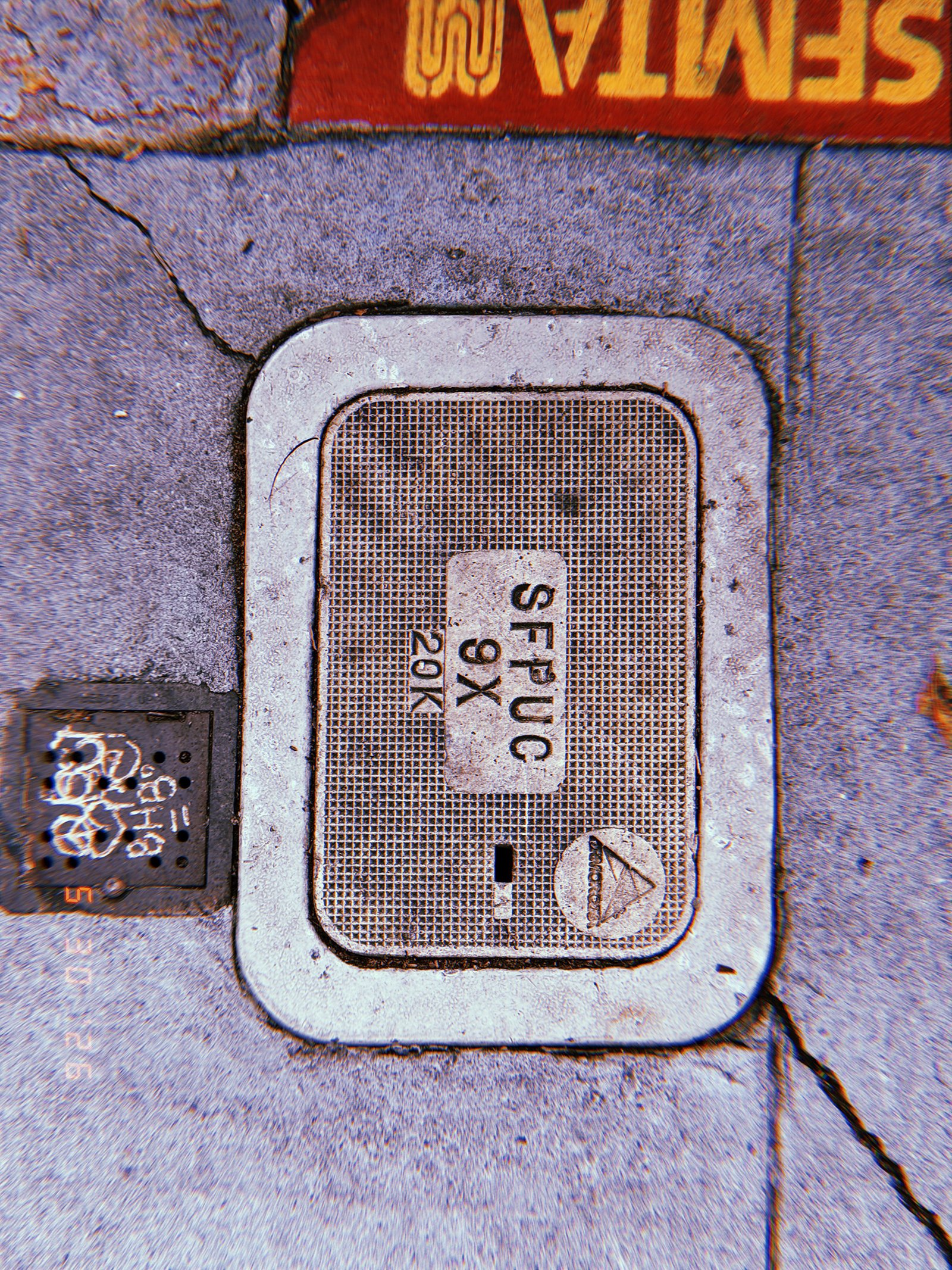
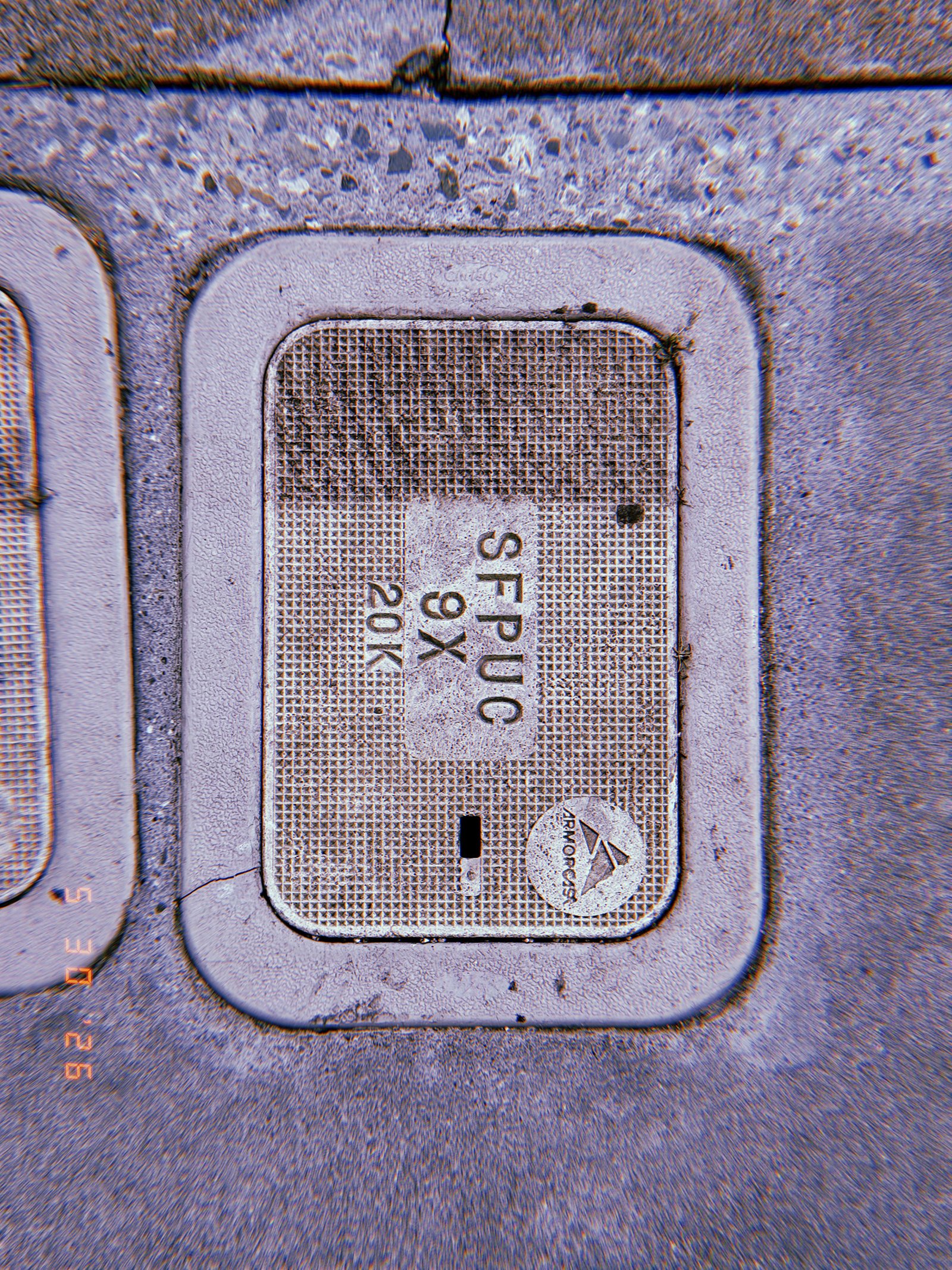
SF Modules – Set 024 – Access Covers – 04
SF Modules — Set 024 “Access Covers”.
A communications access cover is integrated into the sidewalk surface, creating a maintenance interface between the visible city and underground network infrastructure. The textured panel contains utility identification markings and access points used for inspection and service operations. Embedded within the pavement, the cover functions as a standardized component of the city’s communication systems.
SF Modules – Set 024 – Access Covers – 05
SF Modules — Set 024 “Access Covers”.
A communications access cover is installed within the sidewalk surface, forming a maintenance interface between public space and underground network infrastructure. The textured panel includes utility identification markings and access points used for inspection and servicing operations. Embedded within the pavement grid, the cover functions as a standardized component of the city’s communication systems.
SF Modules – Set 024 – Access Covers – 06
SF Modules — Set 024 “Access Covers”.
A communications access cover is embedded between sidewalk paving and asphalt, creating a maintenance interface within the urban surface. The textured panel contains utility identification markings and access points used for servicing underground communication infrastructure. Positioned at the boundary of different surface materials, the cover functions as a standardized element within the city’s hidden network systems.
SF Modules – Set 024 – Access Covers – 07
SF Modules — Set 024 “Access Covers”.
A communications access cover is installed flush within the sidewalk surface, forming a maintenance interface between public space and underground network infrastructure. The textured panel contains utility markings, identification labels, and access points used for inspection and service operations. Embedded in the pavement, the cover functions as a standardized component within the city’s hidden communication systems.
SF Modules – Set 024 – Access Covers – 08
SF Modules — Set 024 “Access Covers”.
A utility access cover is installed flush with the sidewalk surface, providing controlled entry to underground communications infrastructure. The textured panel contains service identifiers and maintenance markings that distinguish its operational function within a larger network system. Embedded within the pavement, the cover serves as an interface between visible urban space and concealed technical infrastructure below.
SF Modules – Set 024 – Access Covers – 09
SF Modules — Set 024 “Access Covers”.
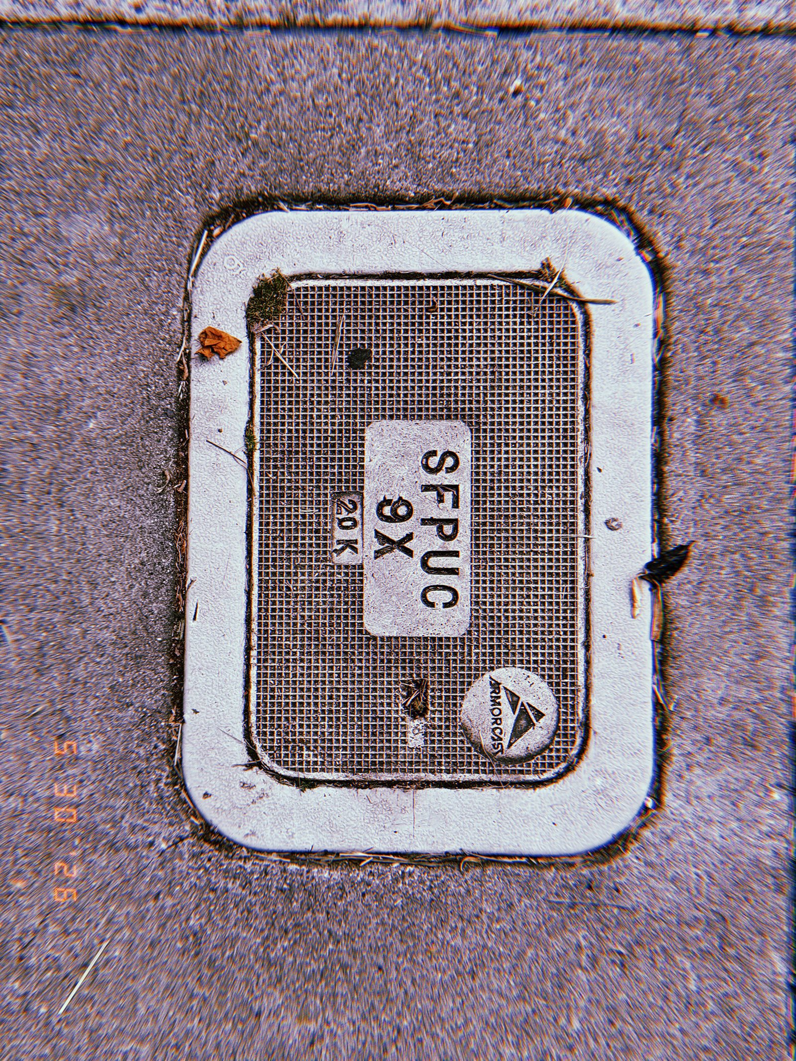
A utility access cover is installed flush with the sidewalk surface, providing controlled entry to underground communications infrastructure. The textured lid carries service markings and identification labels, while surrounding wear and accumulated debris reveal its long-term integration within the urban environment. The cover functions as a maintenance interface between surface conditions and concealed network systems.
SF Modules – Set 023 – Observation Devices – 01
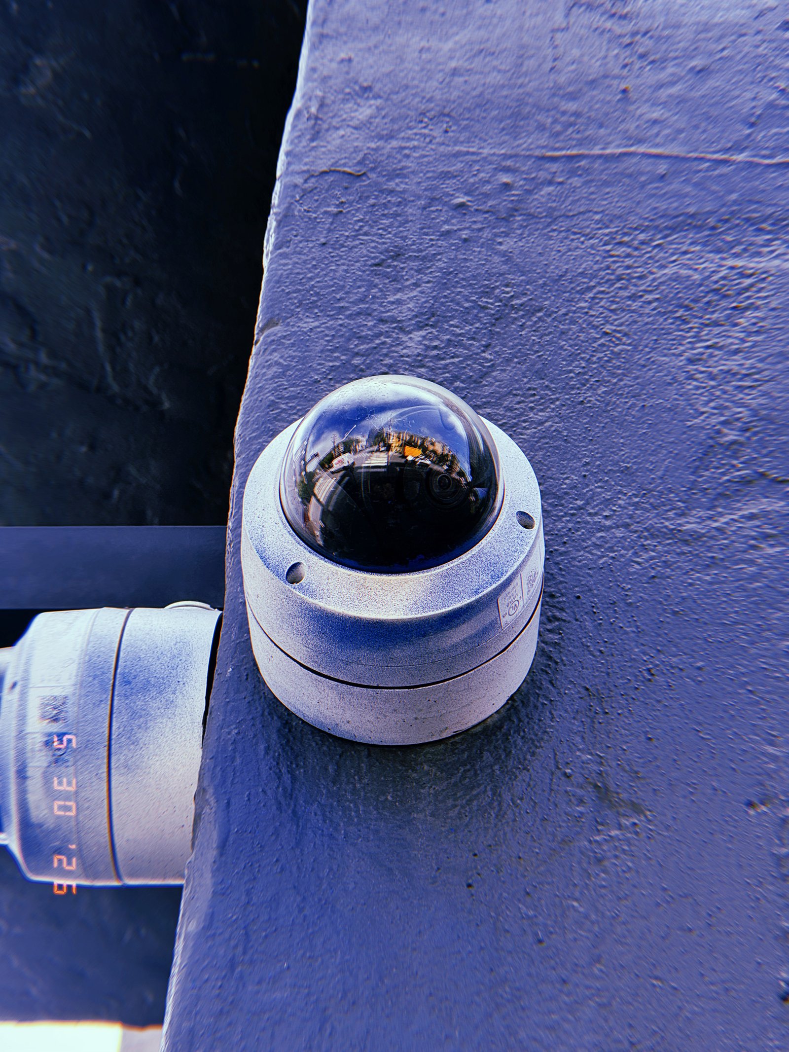
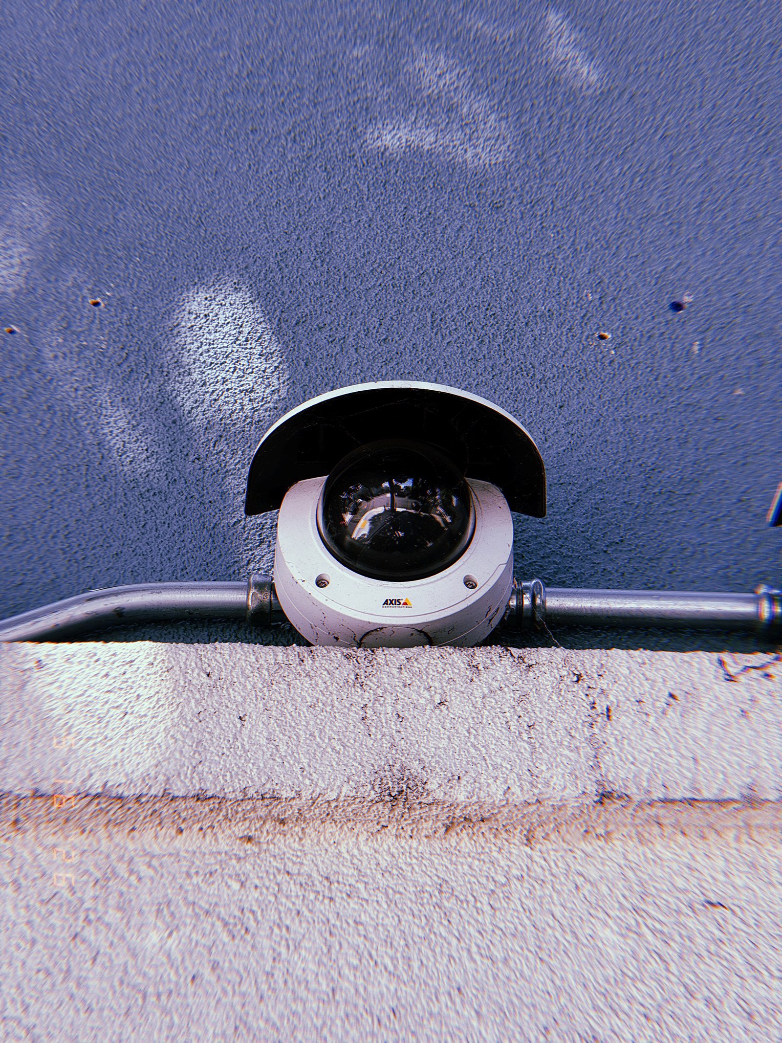
SF Modules — Set 023 “Observation Devices”.
A dome surveillance camera is installed beneath a protective shield and connected to exposed metal conduit integrated into the building structure. Positioned along a wall junction, the device combines monitoring technology with supporting utility infrastructure. The camera operates as a fixed observation point within a distributed network of urban surveillance systems.
SF Modules – Set 023 – Observation Devices – 02
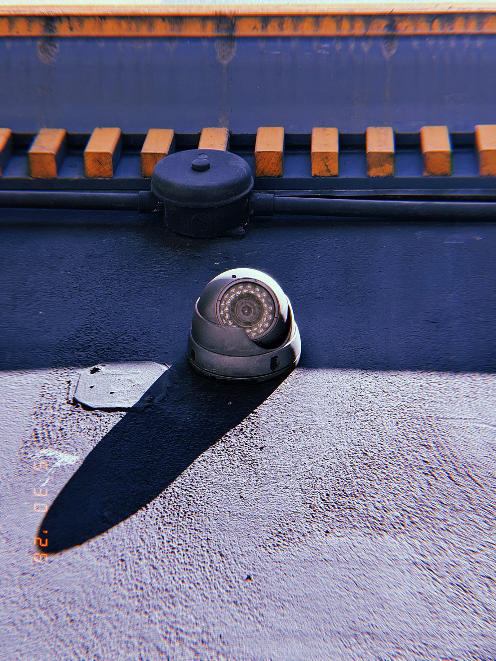
SF Modules — Set 023 “Observation Devices”.
A surveillance camera is installed on a rooftop surface beneath electrical conduits and utility infrastructure. The device projects a long shadow across the textured material, revealing its physical presence within the architectural environment. Positioned as part of a larger monitoring network, the camera extends observation capabilities across the surrounding urban landscape.
SF Modules – Set 023 – Observation Devices – 03
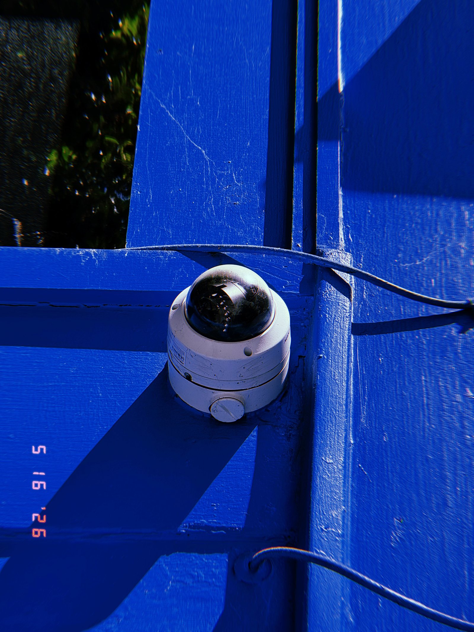
SF Modules — Set 023 “Observation Devices”.
A dome surveillance camera is installed at the junction of structural elements on a brightly painted blue surface. Exposed wiring extends across the architecture, connecting the device to a wider monitoring network. Strong sunlight and sharp shadows reveal the camera as both a functional component and a visible element of urban observation infrastructure.
SF Modules – Set 023 – Observation Devices – 04
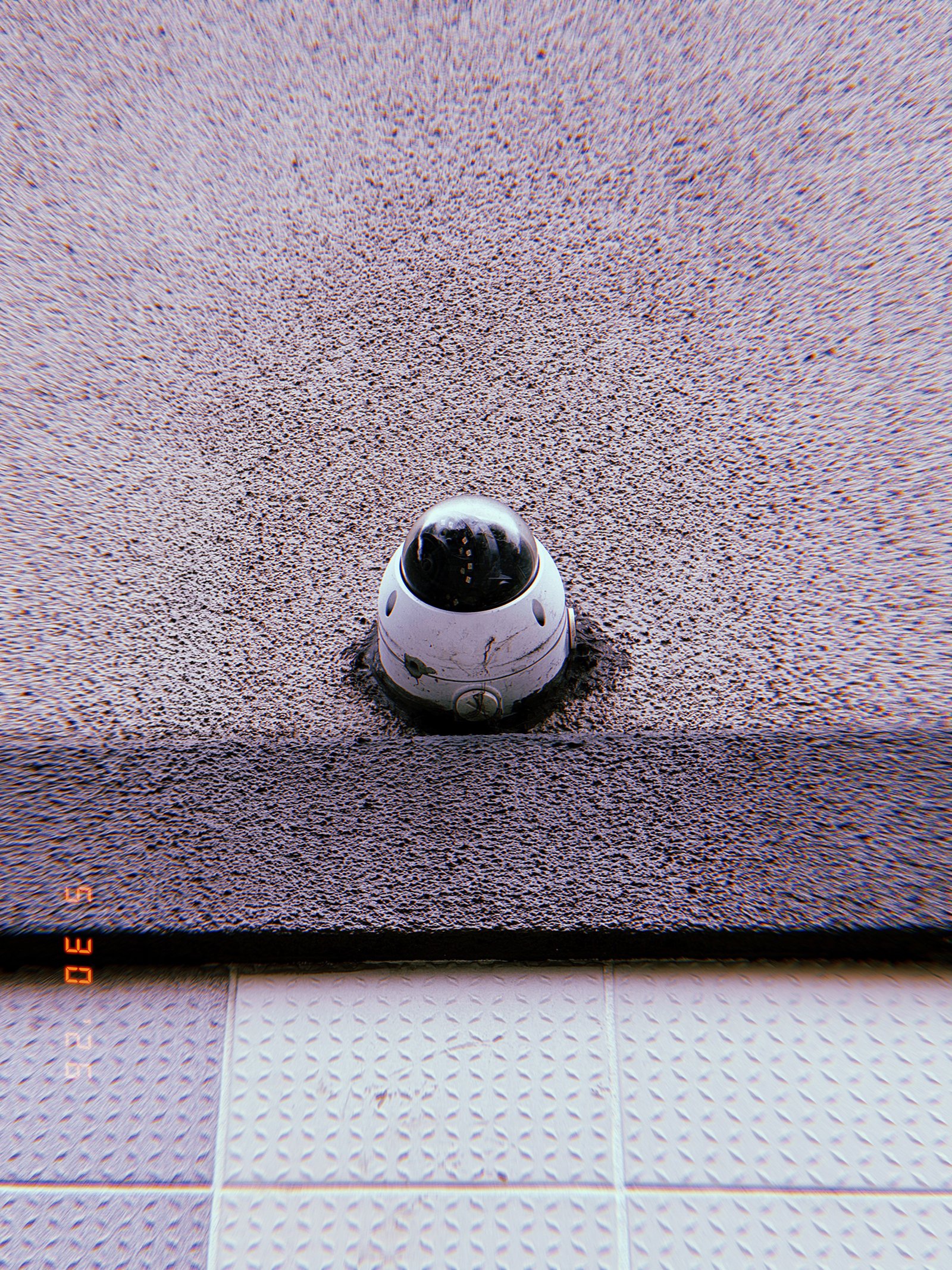
SF Modules — Set 023 “Observation Devices”.
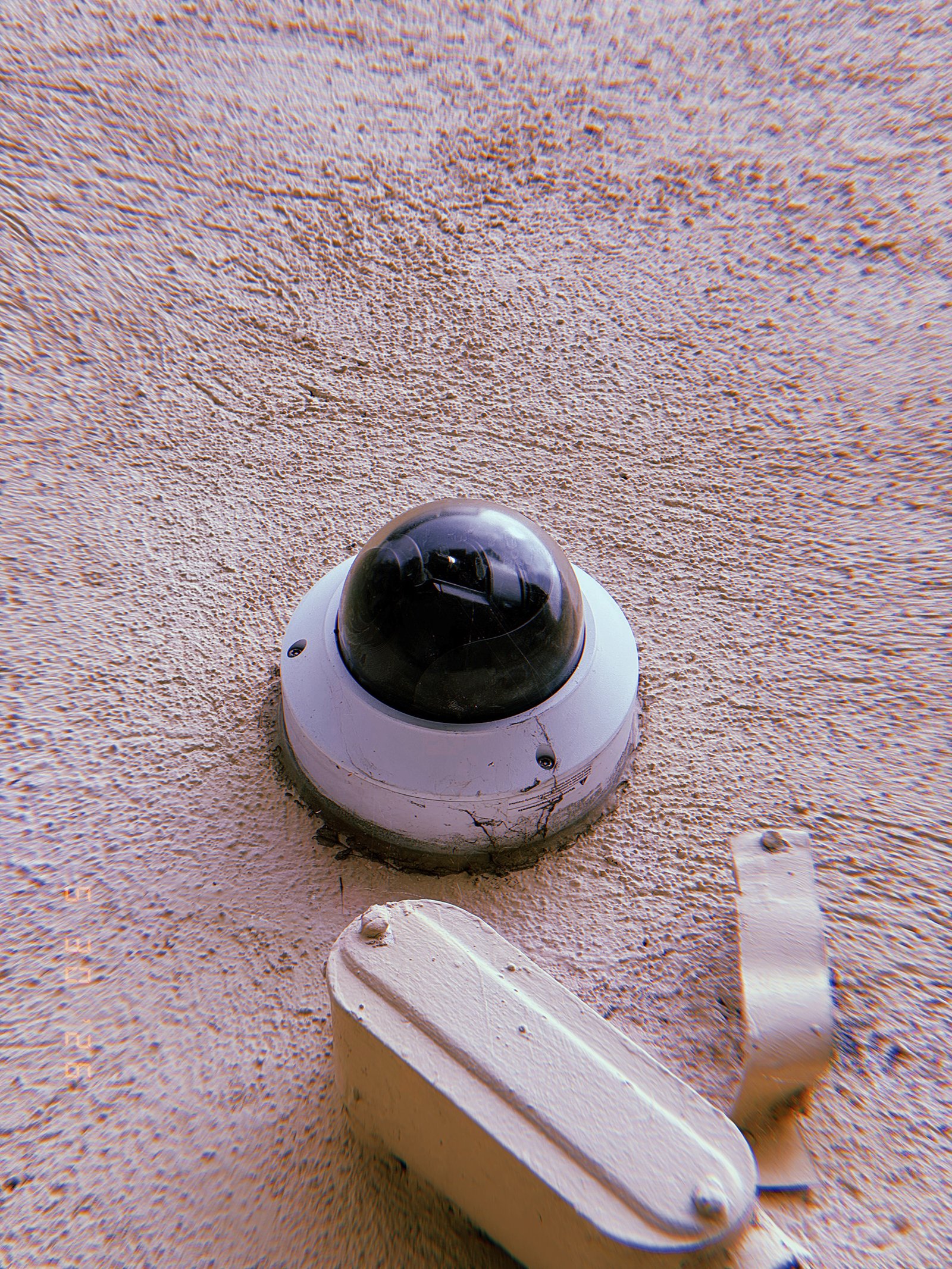
A compact dome surveillance camera is installed directly into a textured building facade above a tiled surface. Embedded at the junction of architectural materials, the device occupies a fixed position within the structure, extending observation functions into the surrounding urban environment. Weathering and surface wear indicate continuous operation over time.
SF Modules – Set 023 – Observation Devices – 05
SF Modules — Set 023 “Observation Devices”.
A compact surveillance camera is attached to a textured building facade, connected by an exposed cable that traces a visible path across the surface. Positioned within the architectural skin of the city, the device functions as a localized observation point while graffiti markings below introduce traces of human activity and intervention.
SF Modules – Set 023 – Observation Devices – 06
SF Modules — Set 023 “Observation Devices”.
A dome surveillance camera is mounted directly onto a textured building facade. Positioned above utility hardware and integrated into the architectural surface, the device extends observation capabilities into the immediate surroundings. Signs of weathering and accumulated wear reveal the long-term presence of monitoring infrastructure within the urban environment.
SF Modules – Set 023 – Observation Devices – 07
SF Modules — Set 023 “Observation Devices”.
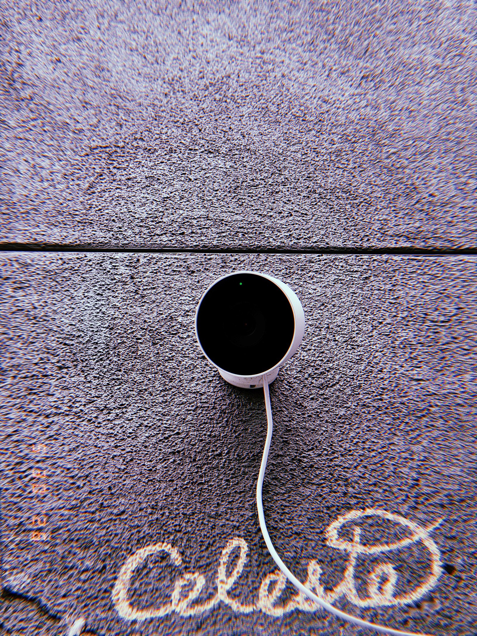
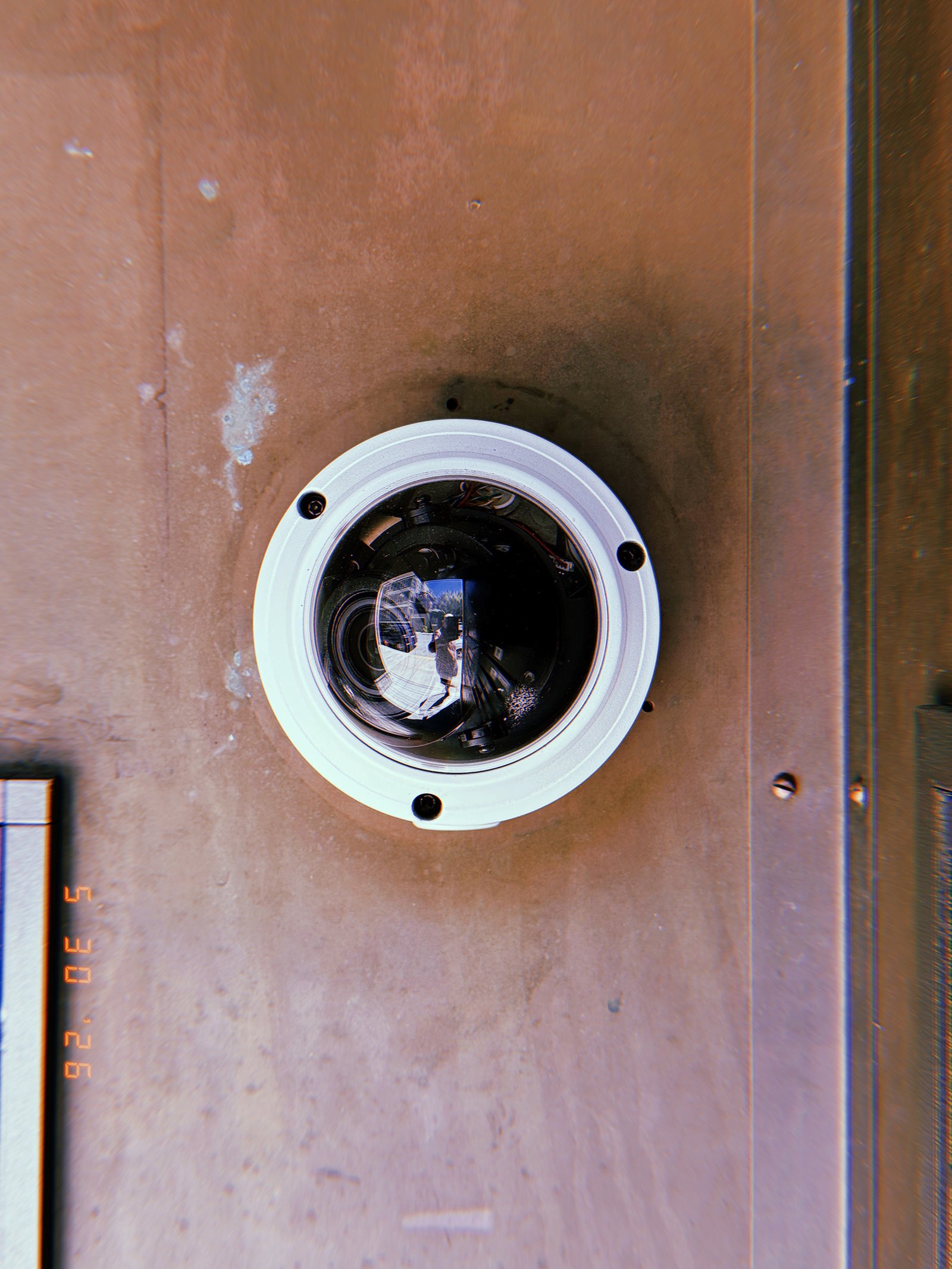
A surveillance camera is installed flush against a building surface, reducing the distance between observation infrastructure and the space being monitored. Unlike fully opaque dome housings, the transparent enclosure exposes parts of the internal optical system while maintaining physical protection. The device functions as a visible point of observation embedded directly within the urban environment.
SF Modules – Set 023 – Observation Devices – 08
SF Modules — Set 023 “Observation Devices”.
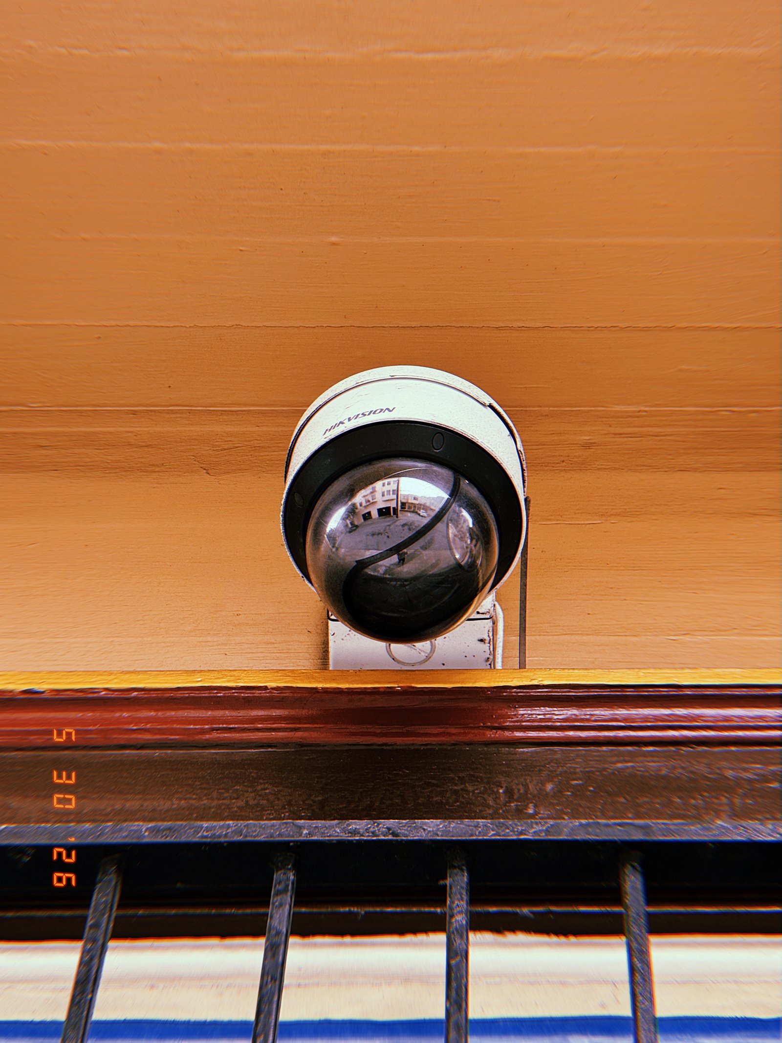
A surveillance camera is positioned above a window and protective metal bars, extending observation beyond the physical boundary of the building. The elevated placement provides continuous visibility of the surrounding area while the reflective dome conceals the precise direction of monitoring. Observation is integrated into the architecture as a permanent operational layer.
SF Modules – Set 023 – Observation Devices – 09
SF Modules — Set 023 “Observation Devices”.
A surveillance camera is installed at the edge of a building facade, positioned to maximize its field of view across multiple directions. The dark reflective dome conceals the orientation of the lens while simultaneously reflecting the environment it monitors. Observation remains visible as infrastructure, but the specific act of watching is obscured within the device itself.